Hi Ladies and Gents,
I have a question regarding the 33 brake circuit, and perhaps the reason why I have a weak offside rear caliper.
Around 4 years ago I converted my car to disc's at the rear because I was fed up with a weak offside drum performance and it seems that the disc/caliper conversion has made no difference, when I changed the brakes I also put in a new compensator at the same time and set it using a 10kg weight when the car was at ride height.
At the weekend I stripped the pads out or the calipers to find the nearside is 50% worn where as the offside is barely worn, in fact I'd say not at all. The handbrake mech works fine both sides so not a binding/ceased piston.
My question is has anyone got a diagram of the brake circuit from the servo as mine I believe may be wrong, one circuit is direct to the front offside caliper and the second is sent to the nearside inner wing where the line is split 3 ways?, one to the front nearside and the other 2 go to the rear compensator. Is this correct?.
Any advice, tips or help appreciated.
Brake circuit questions
Re: Brake circuit questions
How many outlet ports does your brake master have?
Looking at my Red Haynes manual.....
The earlier cars had 3 outlets (one each to the fronts, and one to the rear with a compensator)
Later cars had 4 outlets, one to each wheel
Looking at my Red Haynes manual.....
The earlier cars had 3 outlets (one each to the fronts, and one to the rear with a compensator)
Later cars had 4 outlets, one to each wheel
Re: Brake circuit questions
Hi alfadave,
Mine has 3 outputs 1 direct to front left, one to a 1 in 2 out (t piece) which 1 output is the front right and the 2nd out to one side of the compensator and finally the last servo out goes to the compensator also?, now looking at the pipe work I reckon at some point in the cars history someone change the configuration. I really need a diagram to check I guess.
Mine has 3 outputs 1 direct to front left, one to a 1 in 2 out (t piece) which 1 output is the front right and the 2nd out to one side of the compensator and finally the last servo out goes to the compensator also?, now looking at the pipe work I reckon at some point in the cars history someone change the configuration. I really need a diagram to check I guess.
Re: Brake circuit questions
Pick up a red Haynes manual on ebay for a fiver.
Look at p.86 for the brake diagram.
Master cyl has 3 outlet ports:-
One outlet to front left.
One to front right.
Last one to rears.
I fit a screw down compensator on the rear line, next to the master cyl for convenience of operation......Ebay/Demon Tweeks etc have them reasonably priced
Look at p.86 for the brake diagram.
Master cyl has 3 outlet ports:-
One outlet to front left.
One to front right.
Last one to rears.
I fit a screw down compensator on the rear line, next to the master cyl for convenience of operation......Ebay/Demon Tweeks etc have them reasonably priced
Re: Brake circuit questions
Compbrake have a decent selection of bias valves, as they call them.
UK made it seems?
Some very cheap Chinese stuff around.....to be avoided I think?
It is the brakes after all!
UK made it seems?
Some very cheap Chinese stuff around.....to be avoided I think?
It is the brakes after all!
Re: Brake circuit questions
That explains why I have a weak caliper, Thanks alfa dave, looking in to getting a manual although I don't think they did a 33 version.
Re: Brake circuit questions
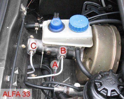
Hi, later 33 have X-circuit with 4 separated lines,
(rear compensator have 2 in and 2 out lines)
also if is still use a pump with 3 out,
one out of the pump goes to the T connector that serves
both one front wheel line and one rear wheel line (opposite side, X-crossed)
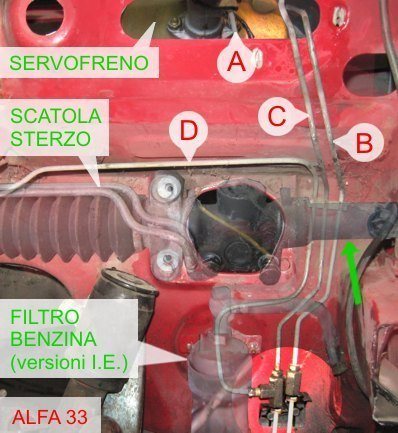
I have these photos, sorry left side drive car (Italy), but you see the principle:
.
.
Ps.: did you used the rear compensator specific for the rear disk versions? it reduce the brake force on rear to compensate the fact that disks have bigger hydraulic pistons than drums)?
.
It is possible you have a clogged brake line that keep a wheel a bit braked?
On another forum there was a similar situations and the clogged line
was confirmed measuring pressure on each line with a tool..
(rear compensator have 2 in and 2 out lines)
also if is still use a pump with 3 out,
one out of the pump goes to the T connector that serves
both one front wheel line and one rear wheel line (opposite side, X-crossed)
I have these photos, sorry left side drive car (Italy), but you see the principle:
.
.
Ps.: did you used the rear compensator specific for the rear disk versions? it reduce the brake force on rear to compensate the fact that disks have bigger hydraulic pistons than drums)?
.
It is possible you have a clogged brake line that keep a wheel a bit braked?
On another forum there was a similar situations and the clogged line
was confirmed measuring pressure on each line with a tool..
Re: Brake circuit questions
Hi Bobkelso,
I have the 3 line output servo that your photos show and the lines are connected the same also. I wasn't aware there is a variation in compensators for disc but will replace the lines front to rear as one may be kinked and they really do need changing. The calipers have been sent off for a re-build and refurb.
I have the 3 line output servo that your photos show and the lines are connected the same also. I wasn't aware there is a variation in compensators for disc but will replace the lines front to rear as one may be kinked and they really do need changing. The calipers have been sent off for a re-build and refurb.